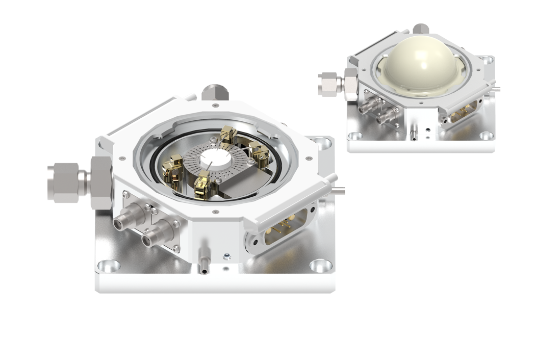
XRD Micro probe system(Environment System with Probes for Mounting XRD Machine)
XRD Micro Probe System is a probe station for in-situ XRD measurement in high temperature and high vacuum. Nextron's unique manual probe makes it possible to apply voltage or read current. This system is great for electric-field-induced phase transition in ferroelectric materials research, resistance analysis during PRAM phase change, ionbased battery analysis, etc.
| Temperature Range | RT – 1000 °C (XRDMPS-CH) | |
|---|---|---|
| -40 – 200 °C (XRDMPS-PT) | ||
| Maximum Cooling / Heating Rate | 30 °C/min | |
| Temperature Accuracy | ±1 °C (XRDMPS-CH) | |
| ±0.1 °C (XRDMPS-PT) | ||
| Temperature Resolution | ±1 °C (XRDMPS-CH) | |
| ±0.1 °C (XRDMPS-PT) | ||
| Sample Stage Dimension | Ø 12.7 mm (XRDMPS-CH) | |
| 19 × 19 mm (XRDMPS-PT) | ||
| Stage Material | Alumina (XRDMPS-CH) | |
| Rhodium coated copper (XRDMPS-PT) | ||
| Dome Material | Peek | |
| Dome thickness | 0.7 mm | |
| Number of Probes | 4 | |
| Probe Tip | Nextron 1K Probe (XRDMPS-CH) | |
| Tungsten Probe (XRDMPS-PT) | ||
| Probe Tip Diameter | 250 µm (XRDMPS-CH) | |
| 50 or 100 µm (XRDMPS-PT) | ||
| Vacuum Test | < 10E-3 mbar at RT (With Rotary Pump) | |
| < 10E-5 mbar at RT (With Turbo Pump) | ||
| Vacuum & Vent Line Fitting | Basic | 1/4, 1/8" Swagelok Tube Fitting |
| Optional | NW16 | |
| Leakage Current | < 100 pA (Coaxial) | |
| < 100 fA (Triaxial) | ||
| Maximum DC Voltage | 300 V | |
| Maximum Current | 1000 mA | |
| Maximum Frequency | 300 MHz (< 3 dB) | |
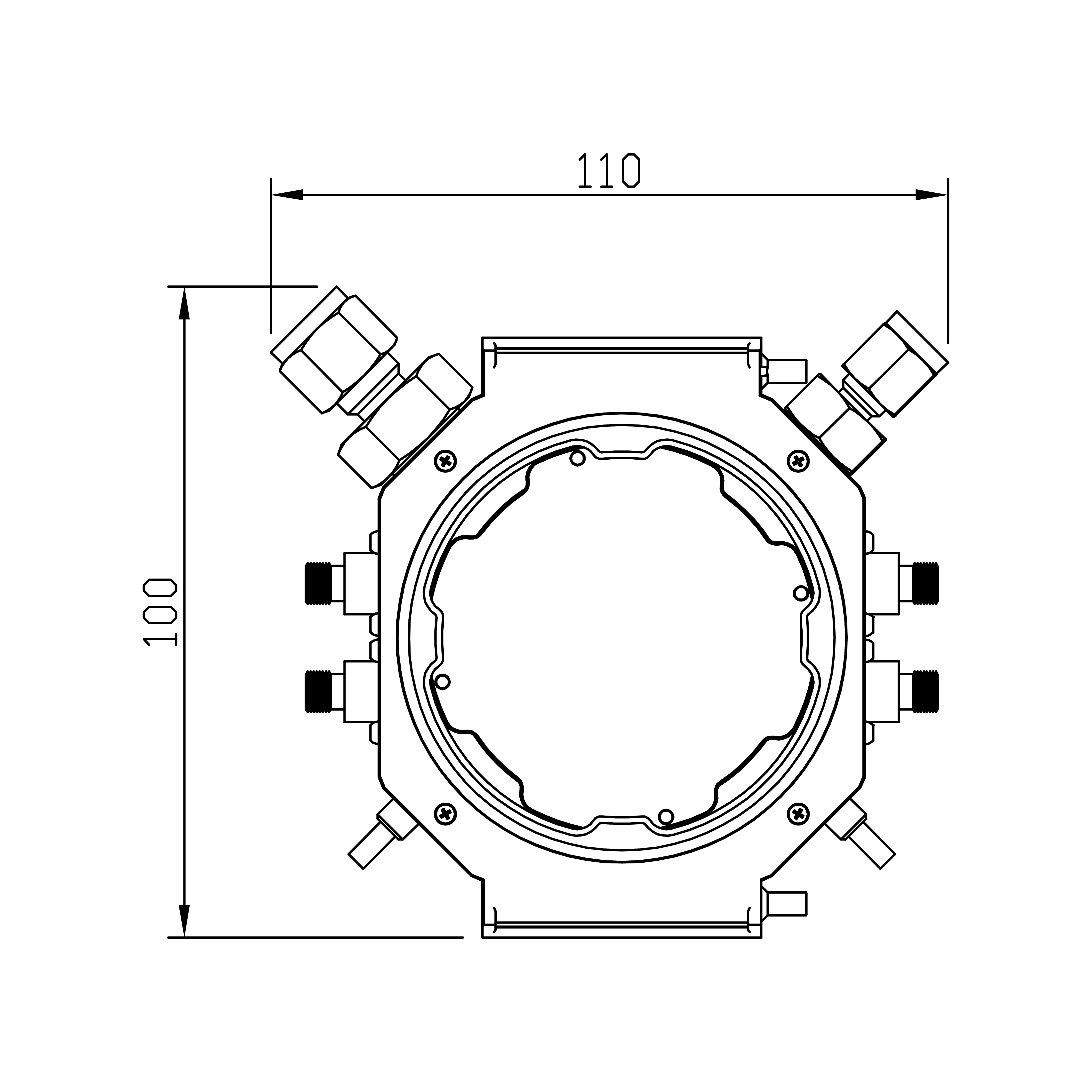
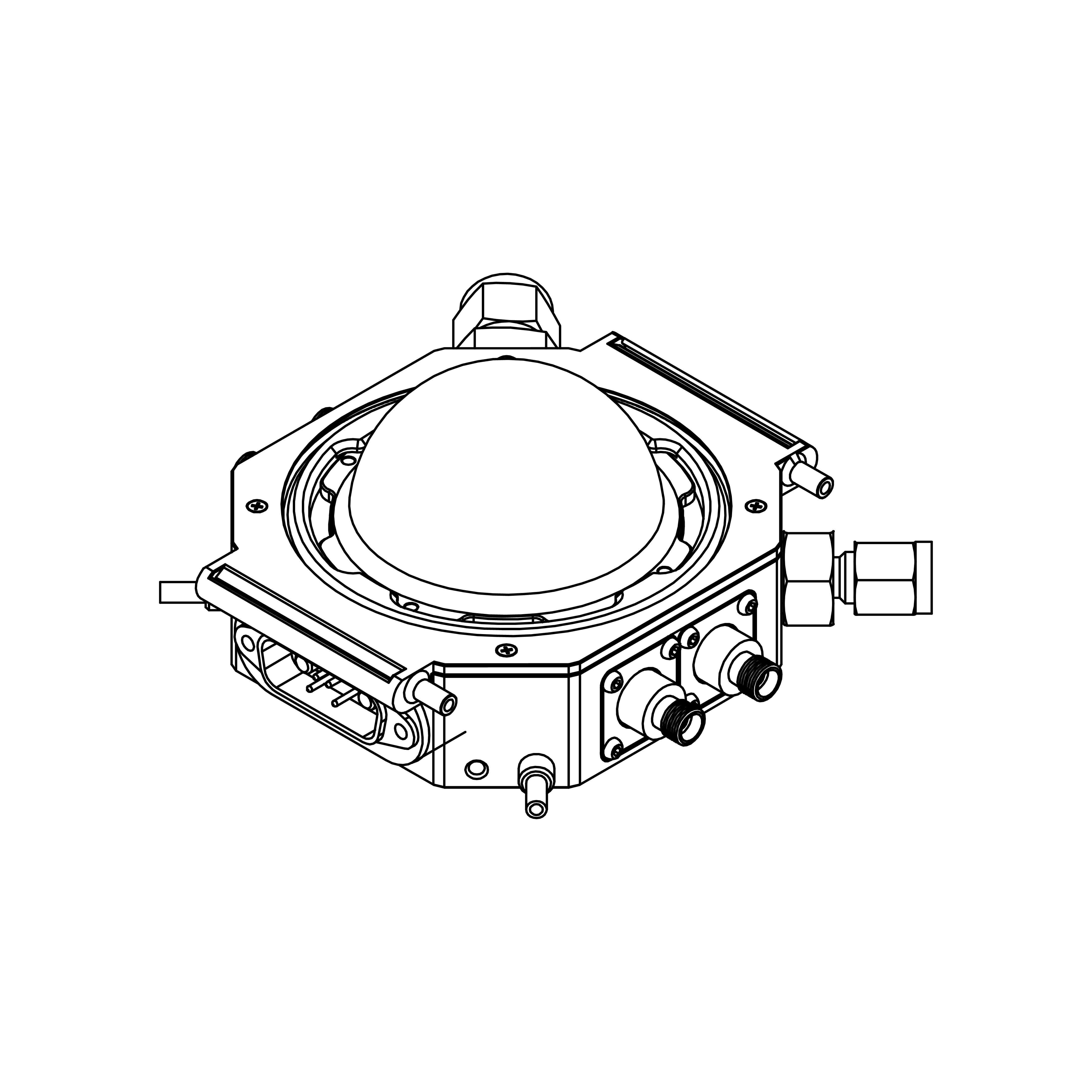
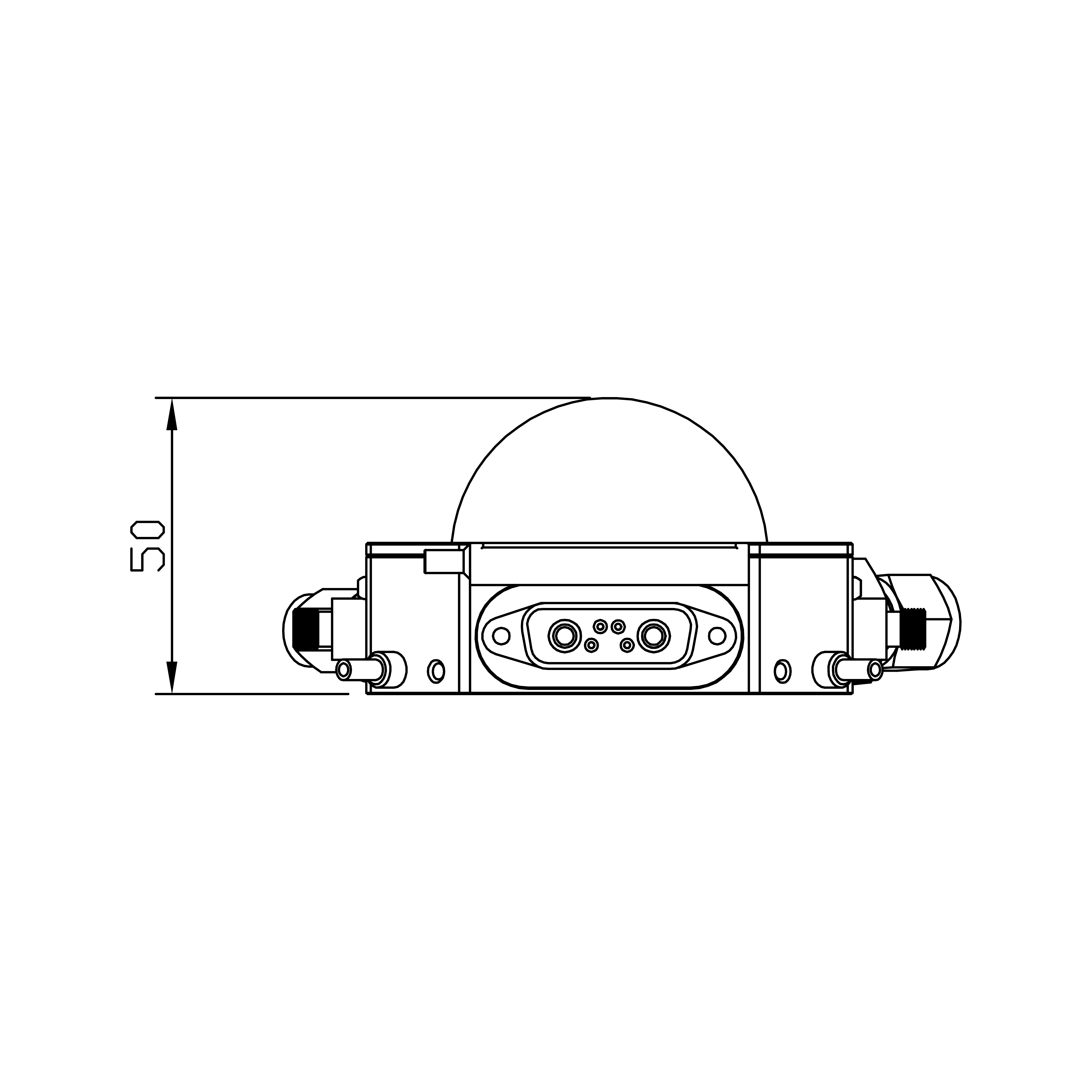
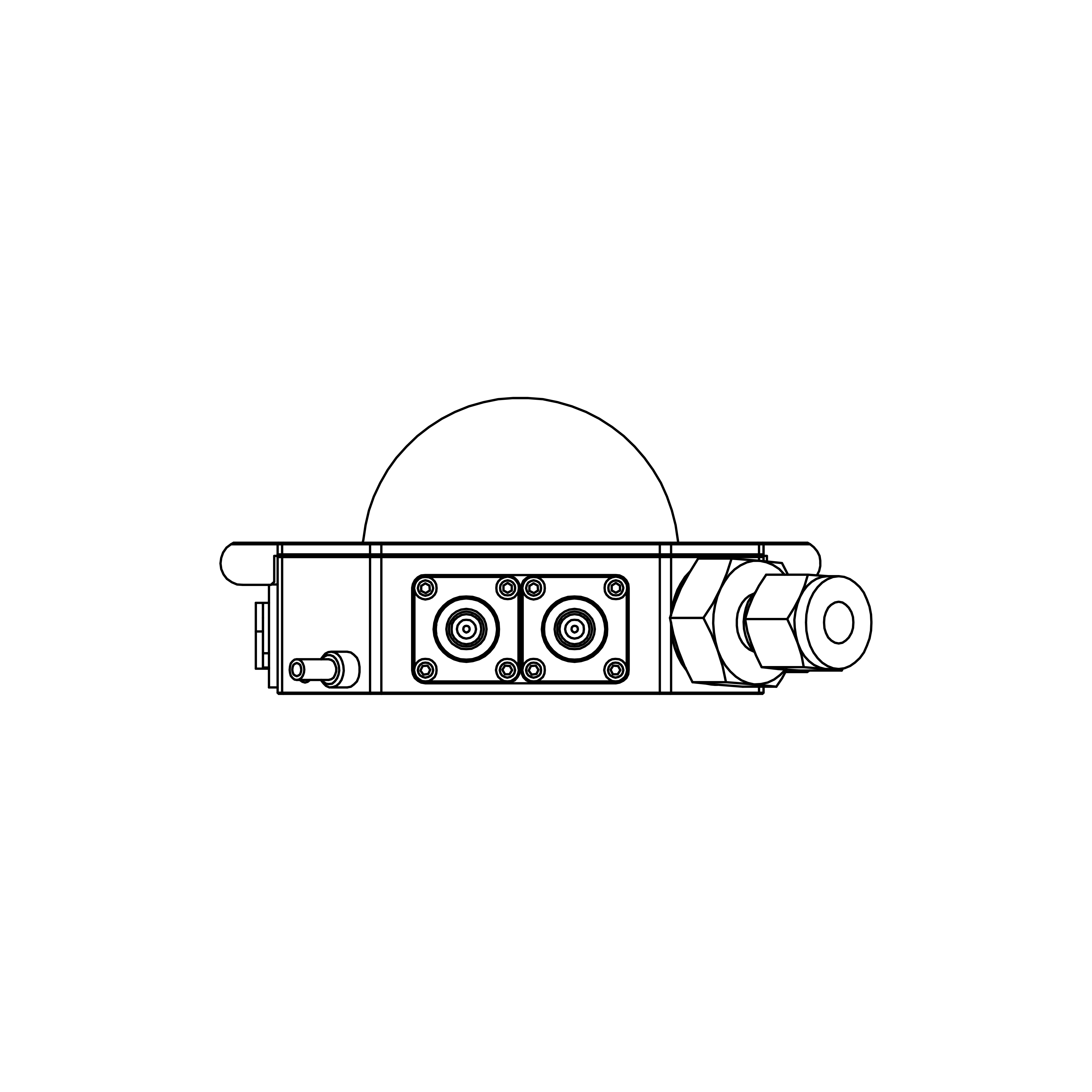
Dimension
(Unit: mm)| Top | 3D |
|---|---|
|
|
| Front | Right |
|
|
Technical Data
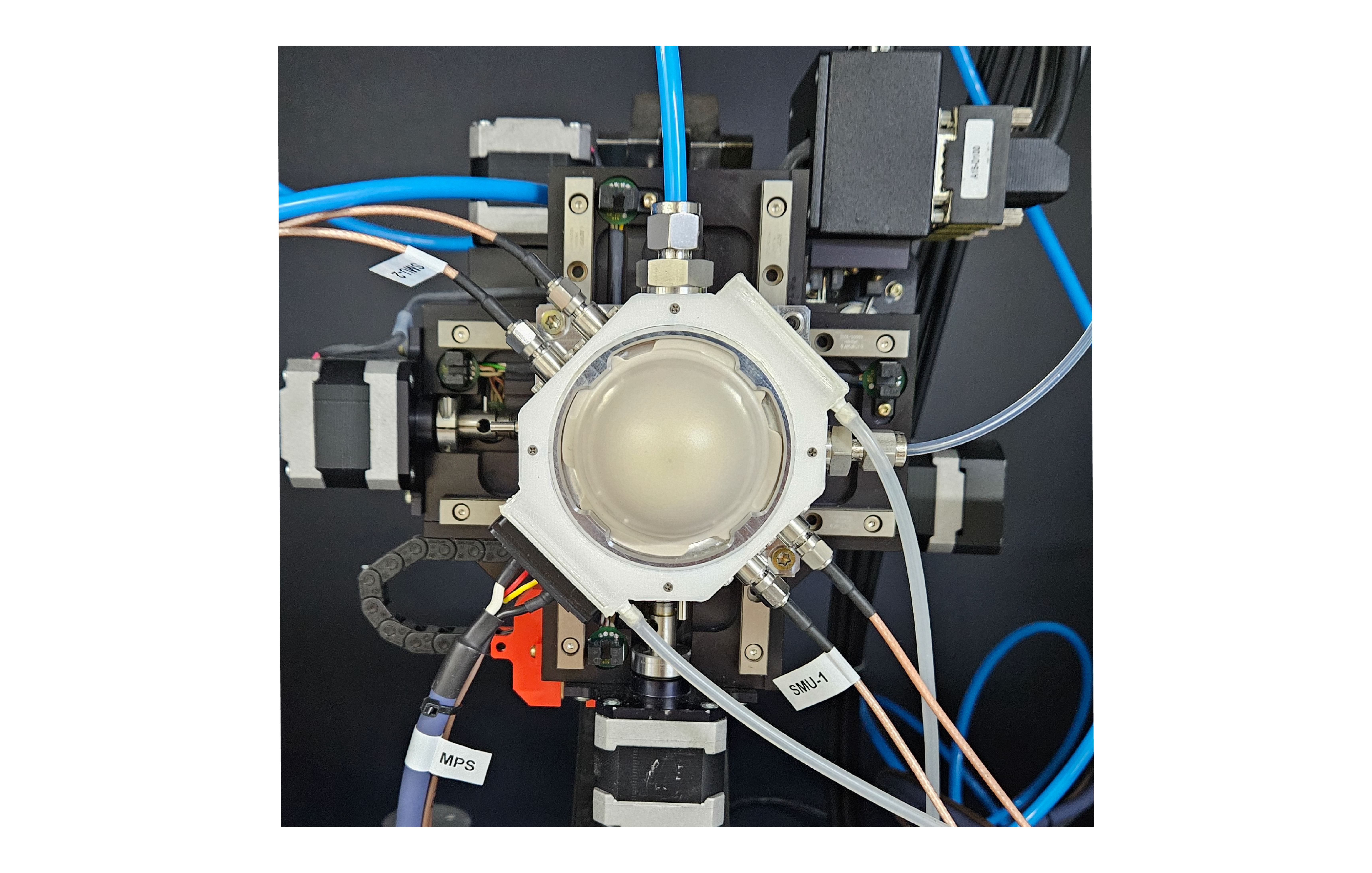
Figure.D8 Bruker XRD set up
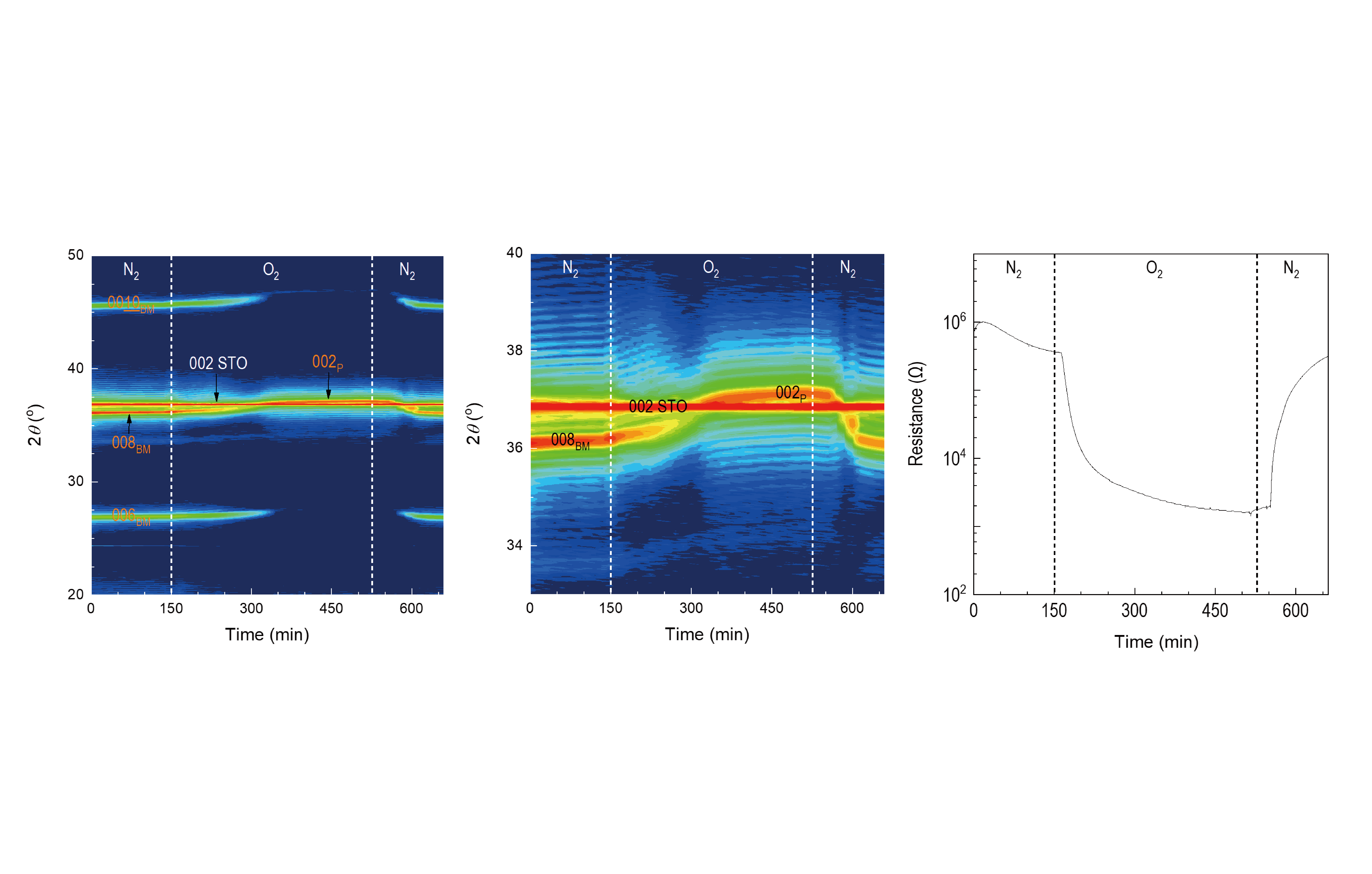
In-situ Observation of Structural Resistance-Changes by Redox Reactions
XRD chamber: Nextron XRD Micro Probe System
Sample: SrFe0.8Co0.2O0.5 on 001 SrTiO3
Beam line: Pohang Accelerator Laboratory 3D beam line
Measurement: Real-time XRD and resistance measurements in supply of N 2(2.5 hrs),
O2(6 hrs), and N2 (2.5 hrs) in sequence. Flow rate was 20 sccm.
Results: The lattice constant of SrFe0.8Co0.2O2.5 thin film
shifted
sequentially to 3.99 Å(N2), 3.90 Å(O2), and 4.00 Å(N2). Associated
resistance changes is observed due to topotactic transformations.
This research work is supported by 'Busan Open Laboratory Business Meeting Market Demands' project.
Technical Data
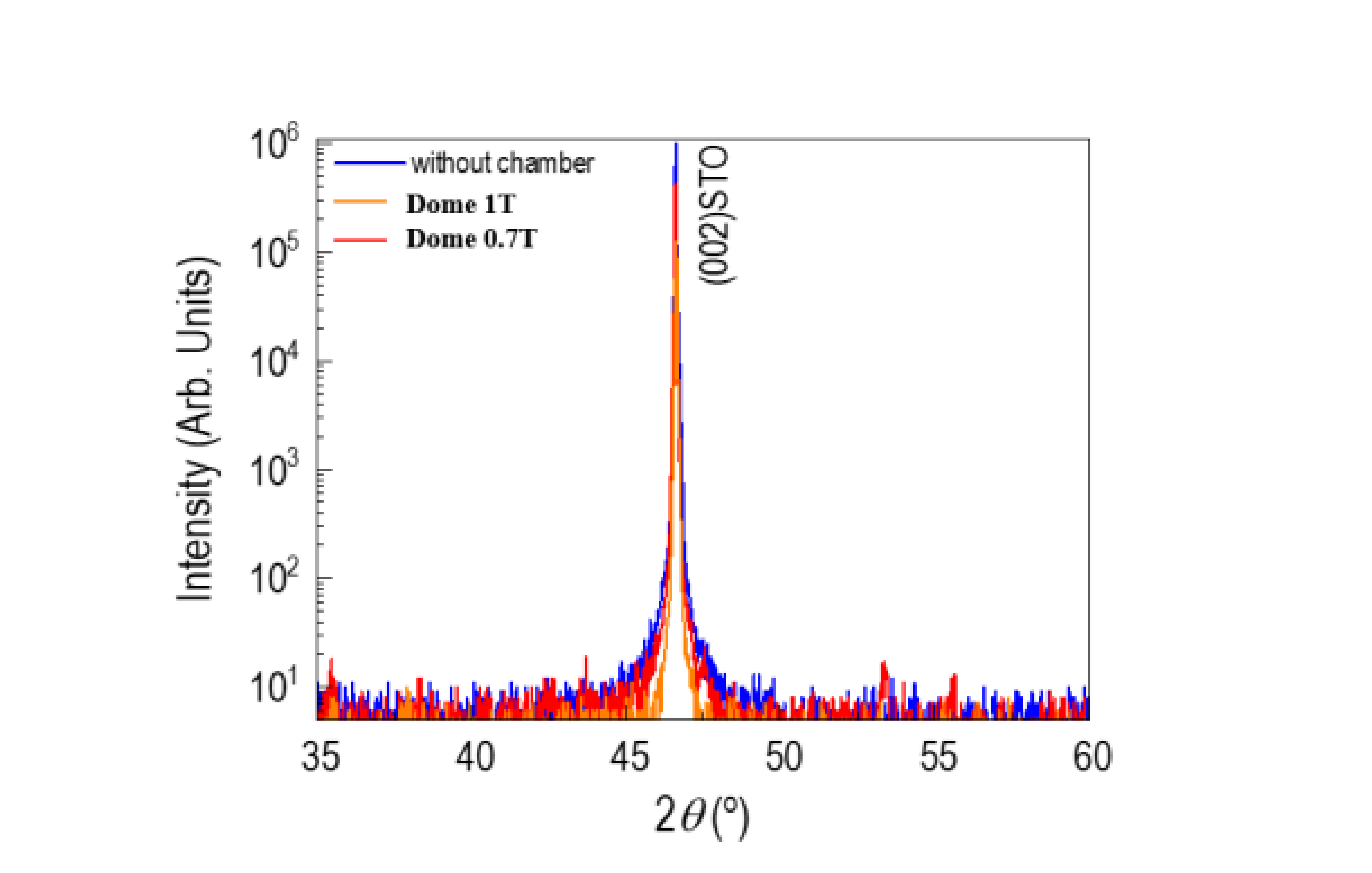
Figure. Comparison of X-ray transmittance according to dome thickness
Results
Transmittance (PEEK dome 1.0 t) : ~15 %
Transmittance (PEEK dome 0.7 t) : ~45 %
Test conditions
XRD : Bruker D8 Discover
Power : 40 kV, 40 mA
Source : Cu Kα1, 1.5046 Å
Dome Temperature Test
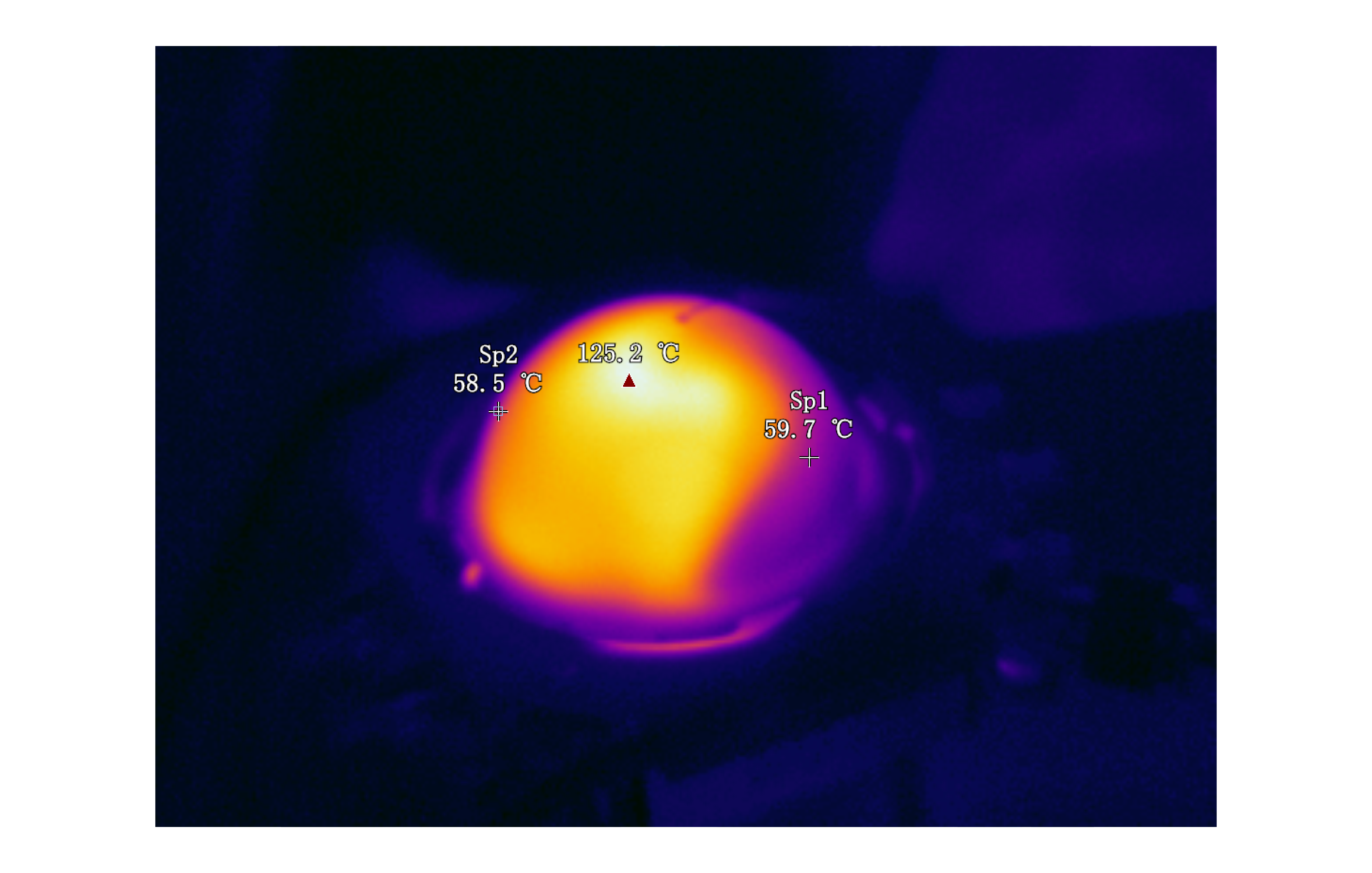
Figure. Using Airblower, the IR camera captures the cooling of the dome temperature in a vacuum state
